

Main application
Pressure vessels or chemical tanks such as hydraulic acid or sulfuric acid.
Main feature
Insensitive to process conditions such as pressure, temperature and specific gravity.
Versatile and easy-to-use controller. (MP2000)
Analog output (2 wire, 4 to 20mA DC) available as standard.
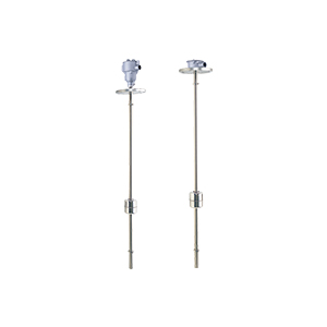
Principle of Operation
LR is comprised of a float and a stem. The float has a magnet inside. The stem incorporates a circuit board with reed switches and resistors placed at regular intervals.
For a rising level, float location and reed switches in operation change as shown in Fig.1, from A(2 switches in operation) to B (3 switches in operation), and then to C (2 switches in operation). For a falling level, from C to B, then to A.
This means that the combined resistance changes as the float rises or falls. When constant current is applied to terminals 1 and 2 in Fig.2, a voltage proportional to the combined resistance is gained on these terminals.
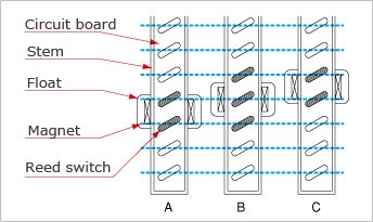
Fig. 1: Operation of float and reed switches
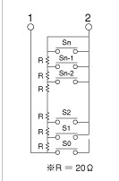
Fig. 2: Circuit in the stem